

A temporal median of five subsequent CAPPI scans is subtracted from each CAPPI scan to prevent interference from stationary structures. Only sampled pixels of each CAPPI scan are used. Applying this after equation (7) leads to
where  is the starting time of the volume scan number s.
The CAPPI scans are then histogram equalized
[63]
to prevent any single, intense aerosol structure
from dominating the cross correlation function.
The histogram equalization transforms the probability density function
of the CAPPI scans to uniform distribution, but does not change the
amplitude order of the data.
The histogram equalization is performed by the following procedure.
All sampled pixels
  in a CAPPI scan
are sorted in ascending intensity order
individually for each level k and time
  .
Then, each pixel is substituted by its normalized index of order.
If
  denotes the
magnitude order of pixel
  in a CAPPI scan at level k and time
  ,
and A denotes
the total number of different digital signal levels in a CAPPI scan, then
the histogram equalization of equation (8) can be expressed as
In an earlier study [45], the histogram equalization was performed with 64 intensity classes (A in equation (9)). Because too few classes will blur aerosol structures and widen cross correlation functions, the number of classes is limited only by the digital levels of the data in this study. Finally, the average intensities are subtracted from each sampled element of the CAPPI scan to reduce zero space lag correlations leading to
where  is the number of sampled elements in the CAPPI scan.
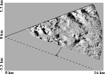
Figure 25 shows an example of a filtered CAPPI scan
ready for correlation calculations.

Figure 25:
A filtered, wind corrected CAPPI scan on August 11, 1989, at 13:02 CDT at
1100 m altitude.
The solid line represents the first and the dashed line the last
shot angle of the scan.
The arrow indicates the wind direction;
its length shows the mean movement correction of air
between the first and last shot.
The bright areas represent increased scattering from aerosols.
The correction for air parcel movements during scanning
shears the scanning area.
A two-dimensional cross correlation function between two subsequent CAPPI scans at the same altitude is calculated in spatial frequency space using the Fast Fourier Transform with zero padded data to prevent end effects [64]. The cross correlation function is divided by the variances of the corresponding CAPPI scans to provide a correctly weighted CCF for the time-average calculations. The cross correlation function between two subsequent CAPPI scans at altitude level k has the functional form
where superscript  denotes complex conjugate;
 and
and  denote
Discrete Fourier Transform and its inverse in
  space, respectively;
std() denotes standard deviation.


