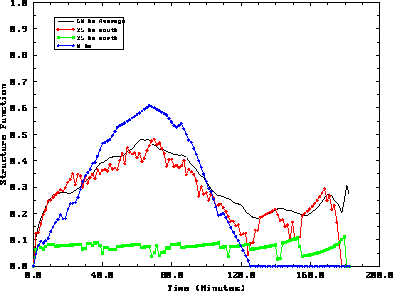


A cirrus cloud-nocloud horizontal structure function was calculated for the three hour time period, 18:08 - 21:20 GMT (Figure 5), using the following equation:
where:

A maximum in the structure function shows a negative correlation between points separated by the lag, i.e. length of the cloud; a relative minimum indicates a positive correlation between points separated by the lag, i.e. the distance between clouds (except at zero separation which is defined to be zero). For the structure function, the width (or length) of the cloud occurs at a local maximum. This was not the half-width of the cloud because if the lag was equal to half the cloud length, an increase in the lag would cause an increase in the structure function. Structure functions were determined both along and across the wind. For the structure functions aligned with the wind, the lag was a function of time. This lag was converted into a distance using the average rawinsonde measured wind speed at the cirrus cloud heights. The along wind structure function was used to determine the length of the cirrus clouds and distance between cirrus clouds. For the cross wind structure functions, the lag was a function of distance. The cross wind structure functions shows the the length of the cirrus clouds and the distance between clouds across the wind.
A series of along wind structure functions were calculated for the 60 km of VIL data for the combined 3 hour time period (Figure 5). The plotted structure functions consist of individual structure functions 25 km north and south of the VIL, a structure function for the cirrus clouds occurring directly above the VIL, and an area averaged structure function. A large amount of variation between the individual structure functions was seen in Figure 5. The along wind structure function 25 km to the north revealed approximately a 6 km (3 minute) length for the cirrus clouds. This structure function had very little variation because 25 km to the north of the VIL the sky had over 95% cloud cover as seen in Figures 3 and 4. The structure function 25 km to the south of the VIL showed a separation between clouds of approximately 262 km (125 minutes) with a cirrus cloud length of 147 km (70 minutes). The cirrus clouds directly overhead had a separation of 262 km (125 minutes) with a 141 km (67 minutes) cloud length. The average structure function for the mesoscale region imaged by the VIL revealed a 273 km (130 minutes) separation between clouds and an average cloud length of 130 km (62 minutes). Smaller scale oscillations were embedded on the individual structure functions. These oscillations show small scale variations in the cirrus features. The effects of the area averaging can be seen in the average structure function where the small scale oscillations have been smoothed out. The half width of the cirrus cloud, 65 km, shows the average distance that a satellite has to move its field of view along the wind direction to view the ground. If a vertically pointing system were used to determine the cirrus cloud structure, the result would be a single structure function defining the whole region. As was seen here, this would not be representative of the volume.

Figure 5: Along wind structure functions for December 1, 1989, from
18:08 to 21:20 GMT, calculated from the VIL simulated RTIs. The x-axis is the
lag in the structure function in
minutes (1 minute is approximately 2100 meters). The y-axis is the
cloud-nocloud structure function. Plotted are: the average along
wind structure function for the 60 km spread (thick solid line), structure
function for a RTI 25 km south of the VIL (circles), structure function
for an RTI 25 km north of the VIL (squares), VIL structure function for
a RTI directly overhead (diamonds). More detailed
explanations are in the text.
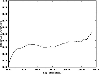
The average cross wind structure function is shown in Figure 6. This structure function increases slowly with the lag because a greater percentage of the cirrus clouds occurred to the north of the VIL. The movement of a widespread cirrus cloud deck from the northwest into a region which previously contained scattered cirrus clouds biased the structure function to larger lag distances. The average cross wind structure function shows cirrus clouds with lengths of 14 km and 43 km. The distance between cirrus clouds was 24 km. As expected, the cross wind structure function was very different than the along wind structure function during this time period. The length of the cirrus clouds along the wind was about 9 times larger than the cirrus cloud length across the wind. The difference in the average structure functions for the two scan directions results in an aspect ratio (length/width) of 9:1 for the cirrus clouds. This aspect ratio suggests that, for this experiment, the cirrus clouds tended to be aligned along the wind. A longer time period has to be analyzed to get a better understanding of the average cirrus cloud horizontal structure.

Figure 6: Cross wind structure function for December 1, 1989, from
18:08 to 21:20 GMT, for the 60 km of VIL data. The x-axis is the lag in the
structure function in
distance (km). The y-axis is the cloud-nocloud structure function. This plot
shows the average cross wind structure function for the 3 hour time period.
The minimum around 24 km shows the average distance between the cirrus clouds.
The peak determines an average cirrus cloud cross wind length of 14 km.
To get a statistically accurate measurement of the distance between clouds the structure function has to become either independent of the lag or a constant which is periodic with the lag. This was only seen for the individual cirrus cloud structure function 25 km to the north of the VIL. The other structure functions gave local measurements of the cirrus cloud structure since the structure function varied with the lag. A longer time period is needed to get better cloud cover statistics for the structure function calculations. This process can be performed on the FIRE II VIL data set.


