Return to the Index.

Transmitted power----------------- 400 mw
Wavelength------------------------ 532 nm (locked to line 1109 of iodine)
Laser pulse width----------------- 40 ns
Repetition rate--------------------- 4 kHz
Reciever field of view------------- 45 microradian
Reciever apperture----------------- 40 cm
Reciever spectral bandpass---------- 6 GHz (pressure tuned etalon)
Aerosol blocking filter bandwidth-- 1.8 GHz (line 1109 of iodine spectrum)
Molecular channel detector--------- Perkin-Elmer SPCM-ARQ-13, QE ~50% @532nm
High gain combined channel detector-- Perkin-Elmer SPCM-ARQ-12
Low gain combined channel detector-- Perkin_Elmer SPCM-ARQ-12FC
Cross Polarization channel detector-- Perkin_Elmer SPCM-ARQ-12FC
Data acqusition---------------------- Photon counting
Altitude resolution------------------ 7.5 m, (ie 50 nsec bin width)
Altitude range recorded-------------- 0---->30km
Typical time resolution-------------- 2.5 s (programable)

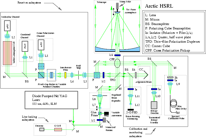
Zemax schematic of the Arctic HSRL showing the optical design and the
various light paths through the instrument. This drawing shows the system
configuration as of 15-Feb-04.
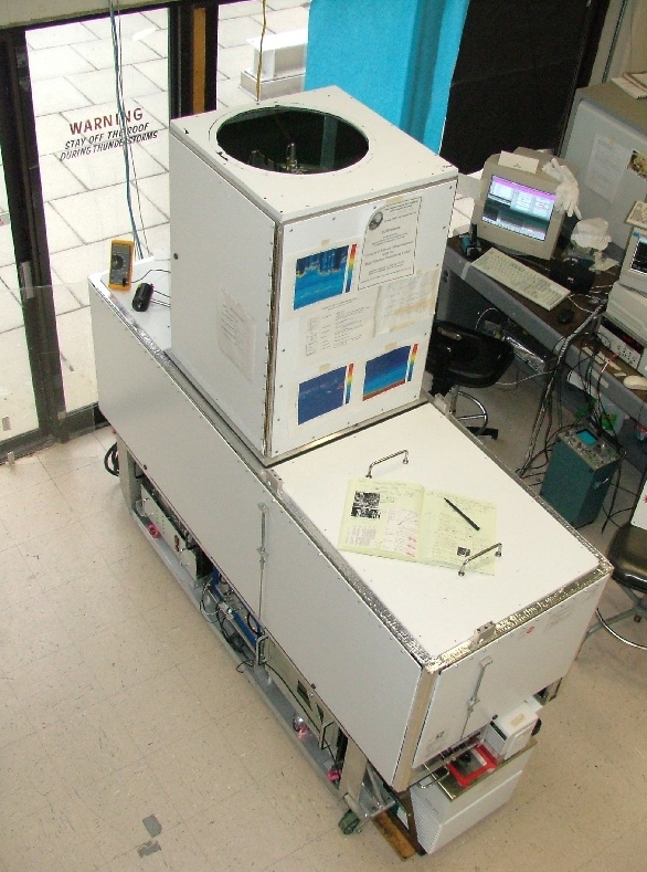
Site requirements for operation of the Arctic HSRL pdf file.
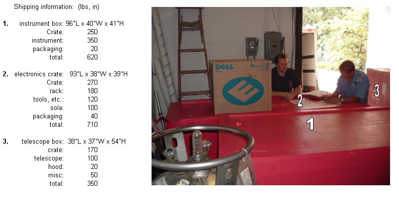
Shipping information for the Arctic HSRL jpg file.
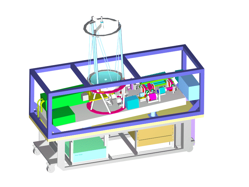
A schematic drawing of the new lidar design (pre-construction
version of design). The received and transmitted beams share a single
telescope. This greatly reduces the difficultly of maintaining system
alignment. However, it generates possible problems with detector
overload from stray transmitted light scattered by optical
surfaces. Initial testing shows acceptable levels of stray light.
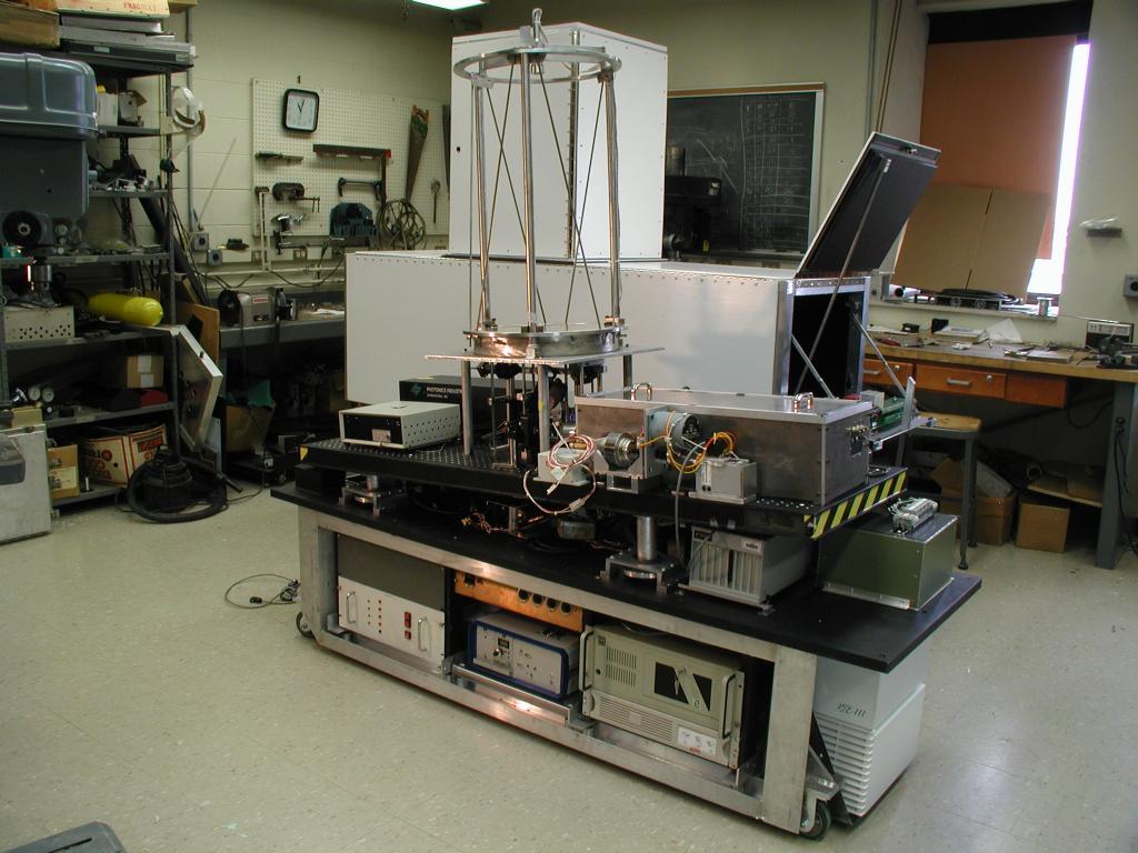
A prespective drawing showing the layout of the Arctic HSRL without
its insulating enclosure. The telescope is tilted 4 degrees from
the vertical to reduce the influence of specular reflections from oriented
ice crystals.
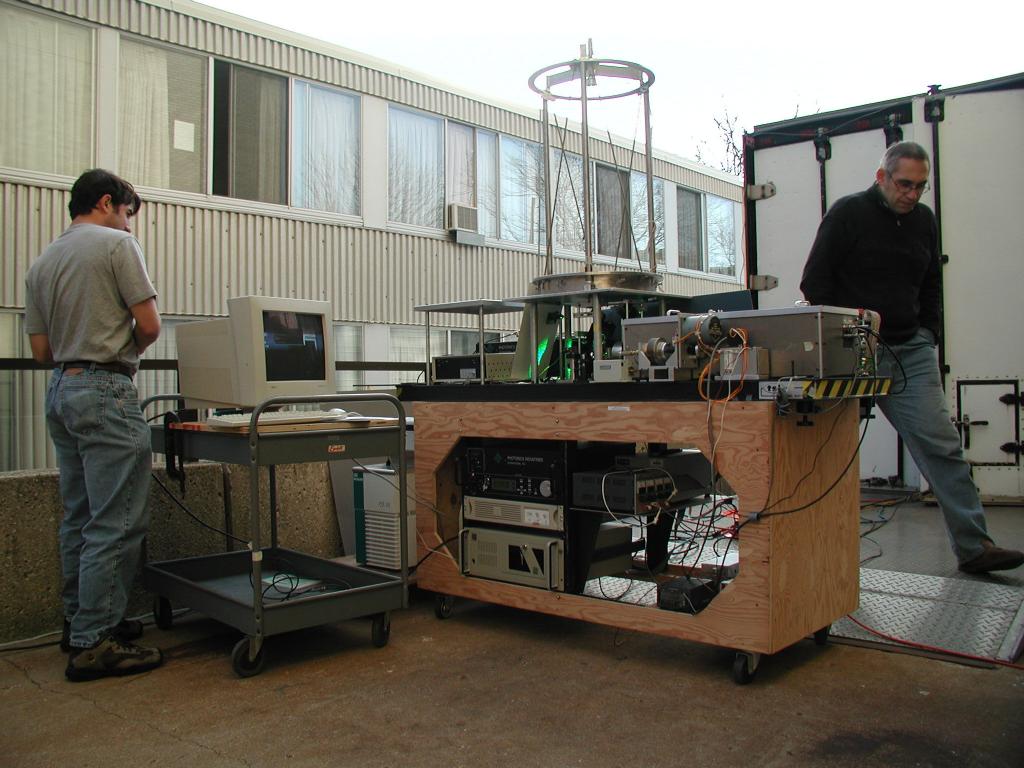
A photo of Igor Razenkov and Bob Holz operating the Arctic HSRL during
initial testing with the system on a temporary table and without the
enviornmental housing which will be required to maintain stable
operation.
A MPEG 4 movie prepared by Igor Razenkov showing early phases of the Arctic HSRL system construction and testing.(37.8 mbyte).