


The HSRL measures optical properties of aerosols by using the backscatter from atmospheric molecules as a calibration target. In the receiver the signal is separated into two separate signals: one proportional to total aerosol and molecular scattering and the other containing the molecular backscattering together with a small aerosol cross talk component. The measured signals are
where
 = signal measured with the combined channel (PMT1 in Figure 6)
 = signal measured with molecular channel (PMT 2 in Figure 6)
 = total number of aerosol and molecular backscatter photons
incident on the receiver field of view
= total number of aerosol and molecular backscatter photons
incident on the receiver field of view
 = aerosol transmission of the molecular channel relative to
the combined channel
= aerosol transmission of the molecular channel relative to
the combined channel
 = molecular transmission of the molecular channel relative to
the combined channel
= molecular transmission of the molecular channel relative to
the combined channel
 = system efficiency factor that includes the optical transmission
of the combined channel and its photomultiplier quantum efficiency
= system efficiency factor that includes the optical transmission
of the combined channel and its photomultiplier quantum efficiency
These two equations can be solved to present the separated aerosol and molecular backscatter signals.
The calibration coefficients  and
and  are obtained from
a system calibration scan. For calibration the system input aperture
is uniformly illuminated with a diffuse light. The receiver
spectral transmission function is measured by scanning the laser wavelength
over an 11 pm wavelength range around the selected iodine absorption peak
and recording the signals (originated from calibration fiber 1 and
calibration fiber 2) with both spectrometer channels (PMT1 and PMT2 in Figure 6).
A calibration scan is performed before
and after each dataset. When system is running for a long period of time
(time
are obtained from
a system calibration scan. For calibration the system input aperture
is uniformly illuminated with a diffuse light. The receiver
spectral transmission function is measured by scanning the laser wavelength
over an 11 pm wavelength range around the selected iodine absorption peak
and recording the signals (originated from calibration fiber 1 and
calibration fiber 2) with both spectrometer channels (PMT1 and PMT2 in Figure 6).
A calibration scan is performed before
and after each dataset. When system is running for a long period of time
(time  3 hours) the system operation is interrupted and
a calibration scan is performed.
An example from a calibration scan is presented in Figure 15.
In addition to the information on the system spectral transmission,
the calibration signals contain information on the beamsplitting ratio
between channels.
Since the signal measured through the iodine cell is flat at the top
of the iodine absorption peak,
the determination of the wavelength of the absorption maximum is
based on the signal from the reference iodine cell (4 cm cell in Figure 5,
calibration fiber 2) and
measured with the PMT1. Otherwise, the signals from the first calibration
fiber are used for the calibration coefficient calculations.
3 hours) the system operation is interrupted and
a calibration scan is performed.
An example from a calibration scan is presented in Figure 15.
In addition to the information on the system spectral transmission,
the calibration signals contain information on the beamsplitting ratio
between channels.
Since the signal measured through the iodine cell is flat at the top
of the iodine absorption peak,
the determination of the wavelength of the absorption maximum is
based on the signal from the reference iodine cell (4 cm cell in Figure 5,
calibration fiber 2) and
measured with the PMT1. Otherwise, the signals from the first calibration
fiber are used for the calibration coefficient calculations.
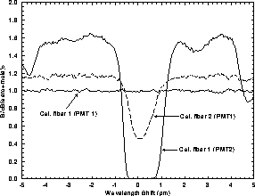
Figure 15: An HSRL calibration scan. The calibration fiber 1 signal
that is detected with PMT2 shows the iodine absorption spectrum of
the 43 cm long iodine cell. The calibration fiber 2 signal
detected with PMT1 presents the absorption spectrum of the 4 cm
long reference cell. The signal from calibration fiber 1 and detected
with PMT1 is used as a reference.
Since the Doppler-broadening of the aerosol backscatter is negligible,
the spectral distribution of the aerosol backscatter can be assumed
to be similar to the spectral distribution of the transmitter laser.
The measured calibration signals can be presented as a convolution
between laser spectral distribution and spectral bandpass of each
channel.
Therefore, the fraction of the total aerosol backscatter detected by
the molecular channel ( ) can be directly obtained from the calibration
signals.
) can be directly obtained from the calibration
signals.

where
 = calibration fiber 1 signal detected
with the PMT2 at the
iodine absorption peak
= calibration fiber 1 signal detected
with the PMT2 at the
iodine absorption peak
 = calibration fiber 1 signal detected
with the PMT1 at the
iodine absorption peak.
= calibration fiber 1 signal detected
with the PMT1 at the
iodine absorption peak.
The fraction of the total molecular backscatter measured by the
molecular channel ( ) is calculated by convoluting the measured
filter function with the calculated molecular spectrum.
) is calculated by convoluting the measured
filter function with the calculated molecular spectrum.
where
 = calibration fiber 1 signal detected with the PMT2
(filter function for molecular channel convoluted with the
laser spectrum)
= calibration fiber 1 signal detected with the PMT2
(filter function for molecular channel convoluted with the
laser spectrum)
 = calibration fiber 1 signal detected with the PMT1
(filter function for aerosol + molecular channel convoluted with the
laser spectrum)
= calibration fiber 1 signal detected with the PMT1
(filter function for aerosol + molecular channel convoluted with the
laser spectrum)
 = calculated molecular spectrum
N = number of points in calibration scan
 = wavelength
 = the wavelength difference between two points in
the calibration scan
= the wavelength difference between two points in
the calibration scan
The divisor on the Eq. 22 is presented as a convolution aerosol and molecular channel. Therefore, the divisor presents the amount of molecular spectrum seen with the combined aerosol and molecular channel. The dividend of the Eq. 22 describes the molecular signal detected through the iodine absorption cell. The molecular spectrum model used in the calculation is presented in a paper by Yip and Nelking [34] and it includes the effects of Brillouin scattering as a function of temperature and pressure.
The accuracy of the calibration coefficients is
mainly limited by the photon counting statistics.
Because the signal transmitted through the
absorption peak is small, the error due to photon counting statistics
dominates the error in
the determination of  .
Therefore, the accuracy of the
.
Therefore, the accuracy of the  is improved by increasing the photon counting statistics at the
absorption peak. Three different ways to increase the photon
counting statistics can be considered. First, the signal at the
absorption peak can be increased by scaling the light with neutral
density filters while scanning.
Second, the amount of aerosol backscatter signal can be
further decreased into a point where the effects of the photon
counting statistics are negligible.
Third, longer averaging time
can be used.
is improved by increasing the photon counting statistics at the
absorption peak. Three different ways to increase the photon
counting statistics can be considered. First, the signal at the
absorption peak can be increased by scaling the light with neutral
density filters while scanning.
Second, the amount of aerosol backscatter signal can be
further decreased into a point where the effects of the photon
counting statistics are negligible.
Third, longer averaging time
can be used.
The disadvantage of using neutral density filters is that
the filters have to be well calibrated and the change in the
value of neutral density filter has to recorded into the
data so that the signal can be reconstructed back to the absorption
spectrum.
The disadvantage of the longer absorption cell is that
the increased cell length will further decrease the amount of
transmitted molecular signal. Also the spectral purity of the
laser limits the observable absorption strength.
In order to be able to obtain a good
photon counting statistics for the signal of the whole absorption peak,
a long
averaging time is required and therefore the total calibration
time would be unreasonable long ( 1h) and during this time
the laser has time to drift. The drift in the laser
output wavelength during the scan effects the width of the
measured absorption spectrum.
1h) and during this time
the laser has time to drift. The drift in the laser
output wavelength during the scan effects the width of the
measured absorption spectrum.
The current HSRL uses a calibration procedure, where
the absorption spectrum is first measured by scanning the laser wavelength
so that  1% photon counting accuracy is achieved for the spectrum
around the
absorption peak.
In order to obtain a high photon counting statistics in short
period of time, the
light from the calibration fibers is optimized so that maximum
number of photons is detected with small pile-up effects at the detectors.
During the scan the location of the peak absorption maximum is detected from
the signal through the 4 cm long reference iodine absorption cell.
After completing the scan, the seedlaser temperature is set back to
the maximum and by using a tuning program (described in more detail in Chapter 5.2)
the laser wavelength is kept at the absorption peak until better than 3%
photon counting statistics is obtained. With this procedure the effects due
to a shift in the laser output wavelength to the width of the
absorption spectrum can be minimized
and the photon counting errors in the determination of the
1% photon counting accuracy is achieved for the spectrum
around the
absorption peak.
In order to obtain a high photon counting statistics in short
period of time, the
light from the calibration fibers is optimized so that maximum
number of photons is detected with small pile-up effects at the detectors.
During the scan the location of the peak absorption maximum is detected from
the signal through the 4 cm long reference iodine absorption cell.
After completing the scan, the seedlaser temperature is set back to
the maximum and by using a tuning program (described in more detail in Chapter 5.2)
the laser wavelength is kept at the absorption peak until better than 3%
photon counting statistics is obtained. With this procedure the effects due
to a shift in the laser output wavelength to the width of the
absorption spectrum can be minimized
and the photon counting errors in the determination of the
 can be reduced from about 20% to 3% within
  10 min
averaging time.
10 min
averaging time.
The atmosphere provides the best reference when the accuracy of the HSRl calibrations is studied. Figure 16 presents an HSRL calibration which is performed simultaneously with data taking. Two different cases are studied. First, a calibration from a thick water cloud is shown. Second, a calibration from clear air is presented. In order to detect the possible range dependence of the calibration, lidar returns from different altitudes are studied. The comparison between calibrations from atmosphere and from the calibration light source also recovers possible misalignments of the system.
The system calibration signal from the iodine absorption spectrum presents a calibration from a pure aerosol target. The agreement between system calibration and atmospheric calibration from a thick water cloud can be seen from Figure 16. Both signals are defined from the ratio of the signal detected through the iodine cell to the signal detected with the combined aerosol+molecular channel. The background corrected, energy normalized signals are used. The data is averaged over a 90 m range. An expected calibration curve from a pure molecular target can be calculated by convoluting the measured iodine absorption spectrum with the calculated molecular spectrum. The calculated molecular calibration together with a measured atmospheric calibration from different altitudes are presented in Figure 16.b-d. The measured absorption spectrum is presented as a reference. For the calculated molecular calibration, the atmospheric temperature, and therefore the width of the Doppler-broadened molecular spectrum, is calculated by using the temperature values obtained by a radiosonde measurement. The signals from higher altitudes are disturbed by the low photon counting statistics, but otherwise a good agreement between system calibration and atmospheric calibration is obtained and no range dependence in the system calibration is observed. The range dependence of the atmospheric calibration would show up as a noticeable deviation from the system calibration.
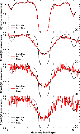
Figure 16: A HSRL calibration scan together with a simultaneous
calibration from the atmosphere.
Figure (a) shows a calibration from a thick water cloud
(thin dashed line) together
with a system calibration scan (thick solid line).
In figures (c)-(d),
the dashed line shows a clear air calibration at
3175 m (b), 5510 m (c), and 7550 m (d). The temperatures at these altitudes
were -11  C (b), -32
  C (c), and -45
  C (d), respectively.
The long dashed line presents
the expected molecular return. The measured calibration scan is
presented as a reference (solid line).
C (d), respectively.
The long dashed line presents
the expected molecular return. The measured calibration scan is
presented as a reference (solid line).


