


As a transmitter, the University of Wisconsin HSRL uses a continuously pumped, Q-switched, injection seeded, frequency doubled Nd:YAG laser operating at a 4 kHz pulse repetition rate [12] (Figure 4). The host cavity is based on a Quantronix model 116 laser. The quarter waveplates on either side of the Nd:YAG-rod are used to generate circularly polarized light in the rod in order to eliminate the spatial hole burning. The narrow bandwidth single frequency operation is achieved by injecting the cw-output of a diode pumped monolithic Nd:YAG ring laser (a modified Lightwave model S-100 seedlaser) into the host cavity through a partially transmitting rear mirror. Measurements have shown, that less than 100 MHz/h frequency drift is achieved. The 4 kHz pulse repetition rate is achieved by using an acousto-optic Q-switch.
The output of the laser is externally doubled by a KTP crystal. The frequency doubled output of the laser is tunable over a 124 GHz frequency range by controlling the temperature of the seedlaser diode. The original analog temperature controlling circuit of the seedlaser has been modified and connected to the microprocessor to allow remote control of the seedlaser Nd:YAG crystal temperature.
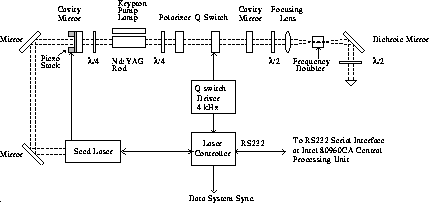
Figure 4: The HSRL transmitter laser.
After frequency doubling, the 532 nm and 1064 nm beams are separated by a harmonic beam separator. Because up to 15% of the residual 1064 nm beam is reflected from the beam separator, a second harmonic beam separator in the laser output (Figure 5) is used to provide more efficient filtering. The remaining 1064 nm beam is cleaned by a spatial filter. The spatial filter also cleans a halo of broader bandpass radiation.
Successful injection seeding requires that overlap
between seedlaser resonance frequency and the frequency of
a host cavity longitudinal mode is achieved.
When the frequency of
a host cavity longitudinal mode is locked to the seedlaser
resonance frequency, the pulse developing out
from the seedlaser signal will saturate the homogeneously
broadened gain medium preventing development of any other axial
modes from the spontaneous emission. Therefore, because one
longitudinal mode is amplified more than any other mode,
a spectrally narrow bandwidth pulse is generated.
Since the seedlaser emissions
used for injection seeding are generally  10 orders of magnitude
stronger than the spontaneous emission, the Q-switched pulse
builds up sooner out of the seed emission than the spontaneous
emission.
The frequency locking between seedlaser and
host cavity is realized by controlling the host cavity
length with a piezoelectric translator.
10 orders of magnitude
stronger than the spontaneous emission, the Q-switched pulse
builds up sooner out of the seed emission than the spontaneous
emission.
The frequency locking between seedlaser and
host cavity is realized by controlling the host cavity
length with a piezoelectric translator.
Because the seeded pulse builds up more rapidly when
the host cavity is tuned to the seed laser frequency, the time between
the Q-switch opening and the subsequent laser pulse (the Q-switch buildup
time) can be used to servo control the tuning of the host cavity [28].
The spectral purity of the outgoing laser pulse can also be monitored
using the Q-switch buildup time.
A microcontroller based
feedback loop seeks to maintain the cavity length by dithering the
rear mirror so that the
minimum Q-switch buildup time is obtained. For each laser pulse,
a small offset voltage is applied to the piezoelectric translator
and the effects to the Q-switch buildup time are simultaneously
monitored.
Based on the Q-switch buildup time the mirror position is
driven towards the minimum time. Statistics on the Q-switch
buildup time is collected at 4 kHz rate, but the mirror
position is dithered at  140 Hz. The amount of dither
is calculated based on the seeding percentage.
The observed Q-switch build up time is
140 Hz. The amount of dither
is calculated based on the seeding percentage.
The observed Q-switch build up time is  4.5
4.5  s and
the difference between seeded and unseeded
conditions is typically
s and
the difference between seeded and unseeded
conditions is typically  500 ns.
Because the spectral purity of the transmitted laser beam is important for
HSRL measurements and because some shots are unseeded,
the information from the Q-switch build up time is used to trigger
the data system only for seeded shots.
500 ns.
Because the spectral purity of the transmitted laser beam is important for
HSRL measurements and because some shots are unseeded,
the information from the Q-switch build up time is used to trigger
the data system only for seeded shots.
The frequency stability of a single-frequency laser is determined by the seedlaser and the stability of the frequency locking is affected by the environment. The injection seeded operation is easily interrupted by mechanical vibrations transmitted through the support structure or through the cooling water or hoses. The effects of change in the optical length of the cavity due to thermal expansions of the support structure and temperature changes in the laser rod are compensated by the active controlling of the main cavity length. The laser is installed on a Super-Invar breadboard supported by a thick honey comb table that is mounted into a vibration insulated frame. The invar breadboard and the honey comb table are isolated from each other by a rubber pad. The laser was delivered with a Super-Invar table, which is thermally stable, but it is found to be acoustically sensitive. The active controlling of the main cavity length already minimizes the effects of changing environmental temperature so that an acoustically more insensitive table might provide a better performance. The mechanical vibrations coming from the laser cooling pump and transmitted into the cavity by hoses and water are isolated by a pressure dumper in the cooling water line. Because the original pressure dumper did not offer enough isolation, an extra damping system was installed. Also extra long elastic plastic water hoses are used to further attenuate the vibrations coming from the laser cooling pump. Furthermore, the temperature of the surrounding environment is stabilized by controlling the air temperature around the laser. The wavelength locking of the laser output to a iodine absorption line is demonstrated later in Chapter 5.2.
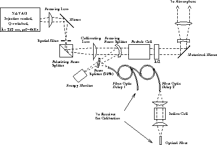
Figure 5: The HSRL transmitter setup. The HSRL transmitter employs
an injection seeded, frequency doubled Nd:YAG laser. A Pockels cell
in the output is used to rotate the polarization of the outgoing
laser beam by 90 degrees for alternative laser pulses. An iodine
absorption cell is used for the frequency locking of the laser
wavelength. A sample of each laser pulse is directed to
a pair of optical fibers, delayed, and injected back to the
receiver for system calibrations. The length of the fibers is
set so that the time-separated pulses can be recorded into the data
profile.