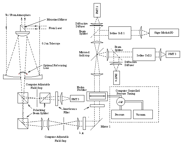
rad field of view for the Gieger Mode APD and PMT2 is defined by a
hole in the mirror 1. The signal transmitted through the hole is
directed to a beam splitter. The signal detected with PMT1 contains
information on the total backscattering from aerosols and molecules.
The aerosol signal directed through the iodine absorption cell and
detected by PMT2 is highly attenuated while the spectral wings of the
Doppler-broadened molecular signal are transmitted with little
attenuation. Signals from PMT1 and PMT2 are used along with
calibration data to derive separate aerosol and molecular lidar
returns [1,2,3]. Multiply scattered photons, which
have been deflected out of the 110 rad field of view, are reflected to another beam
splitter and divided between PMT3 and PMT4 in the same manner as the
110
rad field of view for the Gieger Mode APD and PMT2 is defined by a
hole in the mirror 1. The signal transmitted through the hole is
directed to a beam splitter. The signal detected with PMT1 contains
information on the total backscattering from aerosols and molecules.
The aerosol signal directed through the iodine absorption cell and
detected by PMT2 is highly attenuated while the spectral wings of the
Doppler-broadened molecular signal are transmitted with little
attenuation. Signals from PMT1 and PMT2 are used along with
calibration data to derive separate aerosol and molecular lidar
returns [1,2,3]. Multiply scattered photons, which
have been deflected out of the 110 rad field of view, are reflected to another beam
splitter and divided between PMT3 and PMT4 in the same manner as the
110  rad field of view
signals. Signals from PMT3, PMT4 and PMT5 are used for particle size
and multiple scattering measurements. PMT5 can't be used at the same
time as PMT3 and PMT4 because our photon counting data system
currently has only 4 channels. The refocusing lens in the telescope
output is used to view clouds between altitudes 0.3 km and 2.5 km.
Diffractive diffusers in the optical paths in front of PMT2 and PMT4
serve to compensate for the spatial non-uniformity of the high speed
photo-tubes used for these channels. Notice that the secondary polarizing
beam splitters shown in front of PMT5 and in the lower left hand corner of
the figure are not depicted in their correct orientations--the one in front
of PMT5 is rotated 90 degrees about the optical axis and the one in the
corner directs light out of the page.
rad field of view
signals. Signals from PMT3, PMT4 and PMT5 are used for particle size
and multiple scattering measurements. PMT5 can't be used at the same
time as PMT3 and PMT4 because our photon counting data system
currently has only 4 channels. The refocusing lens in the telescope
output is used to view clouds between altitudes 0.3 km and 2.5 km.
Diffractive diffusers in the optical paths in front of PMT2 and PMT4
serve to compensate for the spatial non-uniformity of the high speed
photo-tubes used for these channels. Notice that the secondary polarizing
beam splitters shown in front of PMT5 and in the lower left hand corner of
the figure are not depicted in their correct orientations--the one in front
of PMT5 is rotated 90 degrees about the optical axis and the one in the
corner directs light out of the page.